Request a quote or need sample?
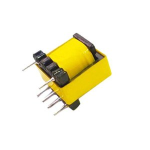
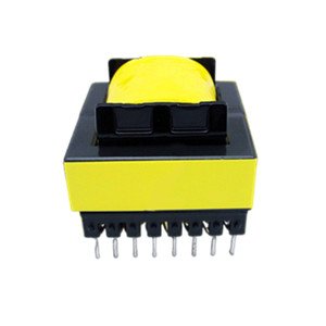
High-frequency transformer
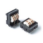
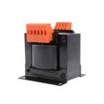
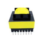
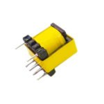
High-frequency transformers are power transformers whose operating frequency exceeds the intermediate frequency (10 kHz). It mainly used as the high-frequency switching power transformer in the high-frequency switching power supply. and it is also used as the high-frequency inverter power transformer in the high-frequency inverter welding machine.
Description
High-frequency transformers are power transformers whose operating frequency exceeds the intermediate frequency (10 kHz). It mainly used as the high-frequency switching power transformer in the high-frequency switching power supply. and it is also used as the high-frequency inverter power transformer in the high-frequency inverter welding machine.
The high-frequency transformer is the most important part of switching power supply. There are many topologies in switching power supply. For example, in the half-bridge power conversion circuit, two switching triodes turn on in turn to generate 100kHz high-frequency pulse wave, and then through the high-frequency transformer for voltage transformation, output AC, the ratio of turns of each winding coil of high-frequency transformer determines the output voltage. In the typical half-bridge transformer circuit, three high-frequency transformers are most conspicuous: the main transformer, drive transformer, and auxiliary transformer (standby transformer). Each transformer has its own measurement standard in the national regulations. For example, as long as the main transformer is more than 200W, its core diameter (height) shall not be less than 35mm. When the power supply power is not more than 300W, the core diameter of the auxiliary transformer can reach 16mm.
Technical parameters
- Rated power: 1000/10000(KVA)
- Efficiency rate (η) : 97%
- Voltage ratio: 400/220V
- Structure: Vertical
- Cooling mode: natural cooling
- Damp proof method: open
- Number of windings: double windings
- Iron core structure: core type
- Cooling mode: dry
- Iron core shape: R
- Power phase number: single phase
- Frequency characteristic: high frequency
Working principle of high-frequency transformers
The high-frequency transformer is a device that converts AC voltage, current, and impedance. When there is AC current in the primary coil, AC flux is produced in the iron core (or magnetic core), so that the voltage (or current) is induced in the secondary coil.
The high-frequency transformer is composed of the iron core (or magnetic core) and coil, which has two or more windings, in which the windings connected to the power supply are called primary coils and the rest are called secondary coils.
The high-frequency transformer is the most important part of switching power supply. The switching power supply generally adopts a half-bridge power conversion circuit. When the two switching transistors work, the two switching transistors turn on to generate the high-frequency pulse wave of 100 kHz and then step down through the frequency transformer to output the low voltage alternating current. The number of turns of each winding coil of the high-frequency transformer determines the output voltage.
The main reasons for electromagnetic interference of high-frequency power transformers are the suction between magnetic cores and the repulsive force between winding conductors. The changing frequency of these forces is consistent with the working frequency of high-frequency power transformers. Therefore, there is no special reason for the high-frequency power transformer with a working frequency of about 100 kHz, which will not produce audio noise below 20khz.
Design principle of high-frequency transformers
In the design of high-frequency transformers, the leakage inductance and distributed capacitance of transformers must be minimized, because the high-frequency transformer transmits high-frequency pulse square wave signal in the switching power supply. In the transient process of transmission, leakage inductance and distributed capacitance will lead to surge current and peak voltage, as well as top oscillations, resulting in an increased loss. Usually, the leakage inductance of the transformer is controlled to 1% ~ 3% of the primary inductance.
The leakage inductance of the primary coil-leakage inductance of the transformer is caused by no complete coupling between the primary coil and secondary coil, between layer and layer, between turn and turn.

